RXPE Thyristor Controlled Resistors (TCBR)
RXPE Thyristor Controlled Resistors (TCBR)
TCBR, short for “Thyristor Controlled Resistors” or “Thyristor Controlled Braking Resistors”, is a kind of power electronic solution to adjust/smooth the ACTIVE POWER (MW) consumption to avoid power generator trips, which is often used in “isolated power grids”.
TCBR is also used/called as Static Watt Compensator (SWC), which is very useful in isolated power grid applcations to maintain a stable power frequency and avoid power generator trips during big load impacts and/or fluctuations.
Isolated power grids are normally weak due to lack of power generations. In this case if loads with big active power impacts can cause significant power frequency variations, which may result in generator trips. It is also known from former practice that, there are several potential risks in operating such “isolated power grid” with “impacting loads”. For example,
- If the load is suddenly lost, what will happen to the power generators?
- What will happen if the load’s power fluctuates during its operations?
- Would the power grid voltage and frequency stay stable?
With all these questions, RXPE had carried out a solution “Thyristor Controlled Braking Resistors (TCBR)” together with our SVCs that can perfectly solve such problems existing in island grids.
RXPE is capable to provide professional technical consultancy services and capable to provide customer with an overall solution to solve all these problems.
Principles
TCBR is a group of resistors that its active power can be controlled and adjusted freely and smoothly as required. It is comprised of one resistor bank (with designed MW power) and one current limiting reactor, as well as one thyristor valve to control the TCBR current, as described in Fig-1. TCBR is controlled by a control & protection system to operate at expected power (0 ~ rated MW).
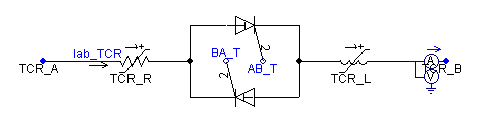
Fig- 1 TCBR Principle Circuit
The following figure shows the power of load and TCBR, we can see that when P_Load is high, P_TCBR is low, when P_Load suddenly drops, P_TCBR rises immediately, which makes the P_Total to be stable at first, if the power of load remains zero for a long time, the power of TCBR decreases slowly to around 0. The decrease speed of TCBR’s power depends on the parameters of the generator.
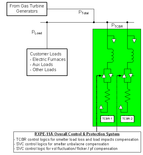
Fig-2 Load and TCBR connections
The resistor banks are comprised of a group of HV resistors with a certain amount of power. These resistors operate under the control of TCBR thyristor valves. The resistors will heat when operate; and such heat will be dissipated by a natural air cooling system or a forced air cooling system.
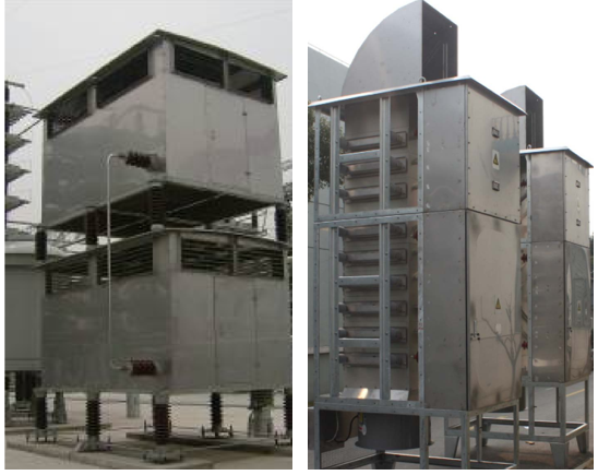
Fig- 3 Typical TCBR Resistors (Left: natural air cooling / Right: forced air cooling)
The Thyristor valve is designed as indoor installation with carefully defined safety clearance.
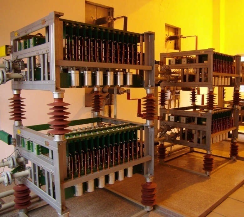
Fig-4 Typical Photo of TCBR Thyristor Valves
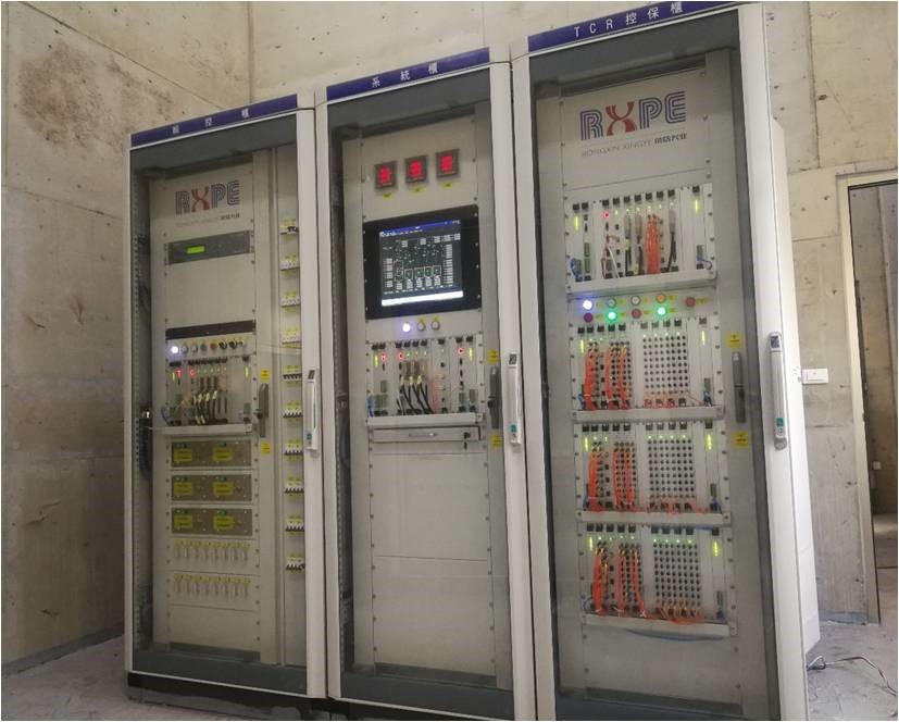
Fig-5 RXPE-11A Control & Protection System
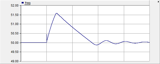
Result: Generator frequency had suddenly rised to 51.6Hz (this had exceeded the power grid frequency limits)
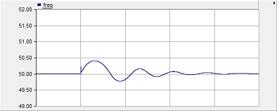
Fig-7 Generator Frequency Curves (Time: 5sec/div) at 72MW Load Rejection and 40MW TCBR Compensation under Auto Control
Result: Generator frequency had been limited to 50.75Hz (compensated to allowable frequency range)
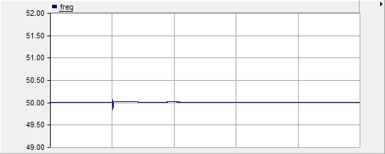
Fig-8 Generator Frequency Curves (Time: 5sec/div) at 72MW Load Rejection and 70MW TCBR Compensation under Auto Control
Result: Generator frequency had been limited to 50.1Hz (the more compensation power, the better frequency performance)
RXPE is capable to provide an overall reactive power (Mvar) + active power (MW) compensation solution to those isolated power grids. Our SVC + TCBR compensation is a perfect solution to solve those voltage and frequency problems, helping customer maintain a good and stable production.
More information please contact us at overseas@rxpe.com or our 24h online service hotline +86-1834 12 12 126.
Liaoning Rongxin Xingye Power Technology Co., Ltd.